On to the rear bulkhead...
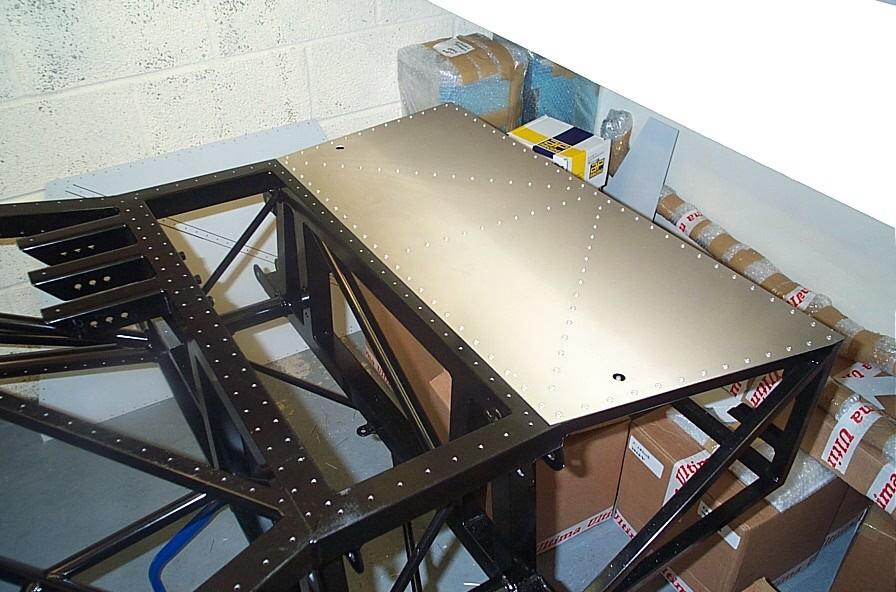
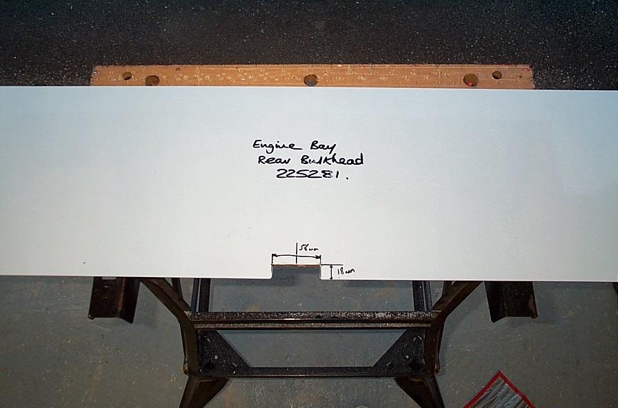
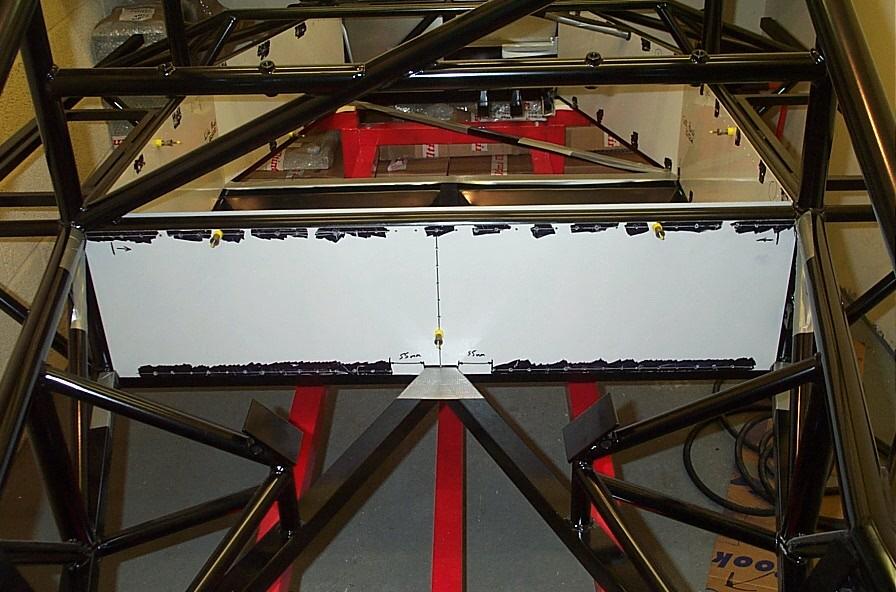
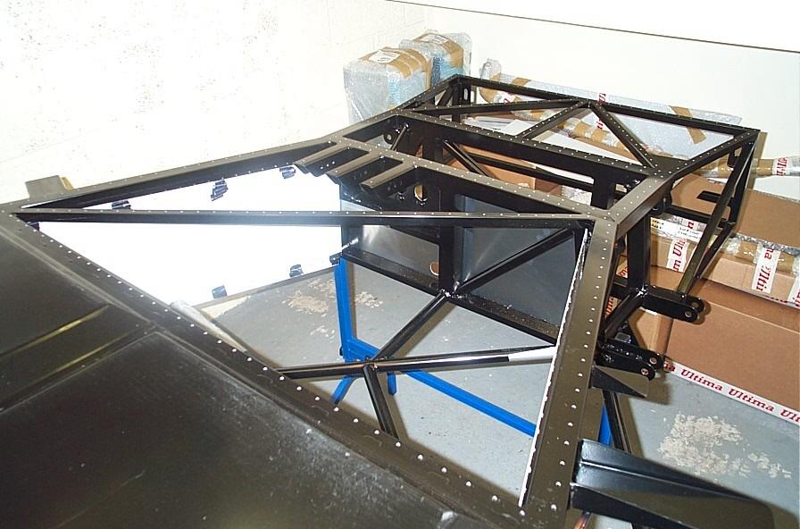
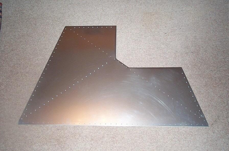
Due to commitments over the weekend (and a small disaster) not much was done unfortunately. But I did manage to get the rear bulkhead fitted to the chassis. This is a slightly odd panel as its fitment is not all that apparent; i.e. the top of the panel does not align to the top of the chassis rail (see pics below). The panel sits approx 10-15mm lower than the top of the chassis rail this allows enough panel overhang on the lower chassis rail (too high and there would be not enough meat to rivet to). Once again I used template to give me a good starting point, this was most useful as the panel is a complete pig to get in and out.
The main material to be removed is in the bottom centre of the panel where the two cross chassis rails meet. As there was plenty of material to be removed out came the air nibbler. This made short work of the notch and after a quick tidy up with a file the panel was ready for pre-fitting. The panel at this point is still a pig to fit some some small notches where made in the corners (still using the template as a guide) to allow easier fitment. Although tight the panel was now in place, but before the panel was going to sot flat some more material was going to need to be removed from the corners, mainly to allow for the welds. Once this was done the height of the panel was the most important consideration, this could be adjusted by the depth of the central notch. Once I was happy with the height consideration for the positions of the rivets was the next step.
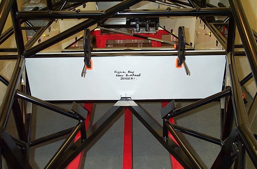
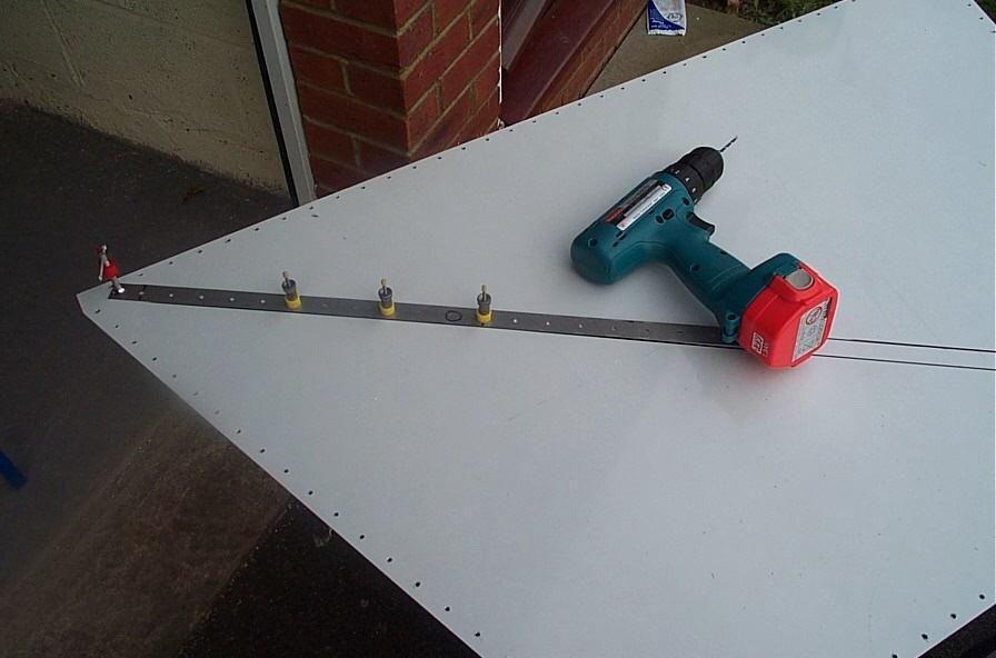
The rivet spacing along the top seems to fit the common 30mm spacing theory. So a line of rivets was made 7.5mm down from the top, this positioned the rivet holes along the centre line of the chassis rail. The vertical line was all so ok for the 30mm spacing (from the top down). The bottom line was going to have to be taken from a different datum. This was going to have to be sorted later as it was now Sunday evening and Scrapheap Challenge was on the TV. All stop until Wednesday evening...
Rear Bulkhead finished...
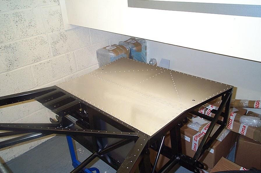
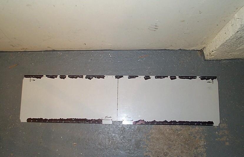
So where was I, ahh the holes on the rear bulkhead. The rivet spacing along the bottom was slightly more difficult as is was awkward to drill close to the corners and the centre, due to the proximity of the chassis rails. After some measurements it appeared a good solution was to start from the centre out and position the first rivet 55mm from the edge of the central cut-out. This positioned the last rivet far enough from the corner to allow sufficient clearance for the 90 Degree Drill (and a rivet gun). Note that the top line of holes also need to allow clearance for the drill at the corners.
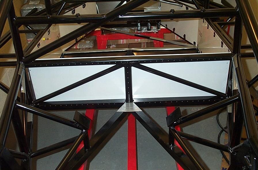
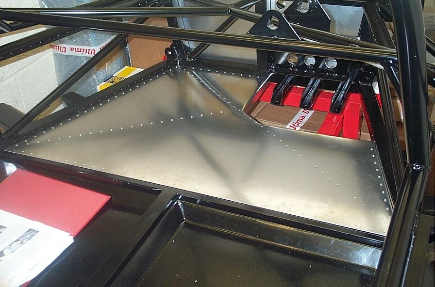
The panel was now re-positioned back in the chassis and the panel aligned. Once in position the top of the panel sat approx 12mm lower than the top of the chassis rail. The panel was clamped into place and the holes were drilled. As a precaution I first lightly drilled (i.e. not a hole) the chassis and removed the panel to ensure that all the holes were going to line up. Looked good to me, so the panel was repositioned and the rest of the holes drilled. All the holes were de-burred and the panel was skin pinned back into place. As this is quite an awkward panel I was very pleased with the result.
With that now done it was time to think about turning the chassis upside down to allow the floor panels to be fitted. Unsure as to whether the chassis would fit back onto the dolly when it was upside down I emailed a fellow builder and he confirmed that when he did his he just put it back on the dolly (thanks CJ). So the weekend is floor fitting time, until then...
So to the Floor then...
All I did was put it back on the dolly... Thanks!
The fun started on Saturday when the chassis had to be inverted to allow the floor panels to be fitted. I had been led to believe that is was possible to place the chassis back on the dolly after it had been inverted, this proved not to be the case. I fact when you look at it (I couldn't as I work away from home) it was obvious that the chassis could not be placed back on the dolly once inverted due to the roll bars etc. So it was off to Machine Mart for some trestles (Toolbox updated). With the top of the trestles covered in bubble rap my mate Geoff gave me a hand (again) to flip the chassis over and place it back on the trestles centrally in the garage.
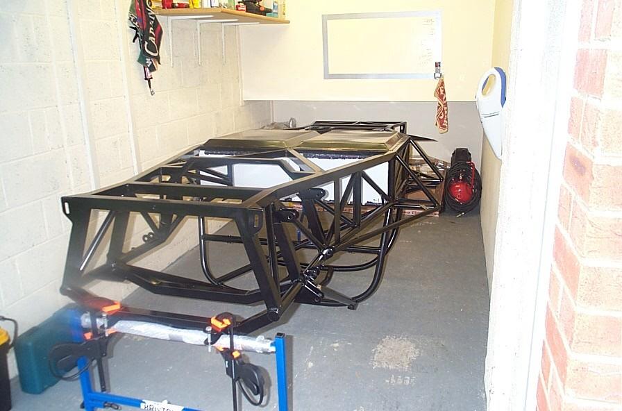
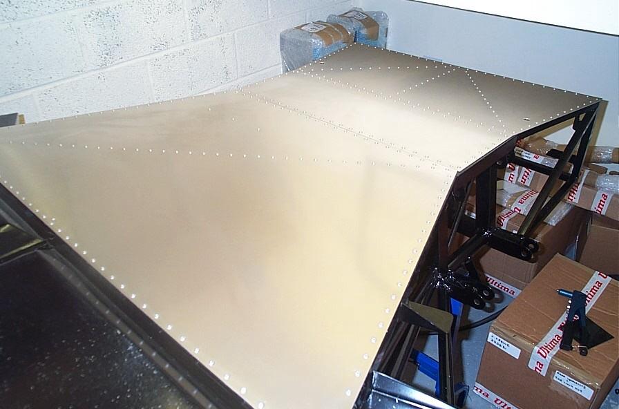
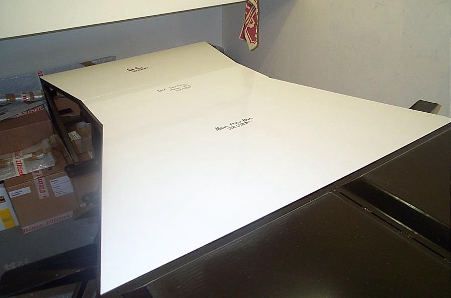
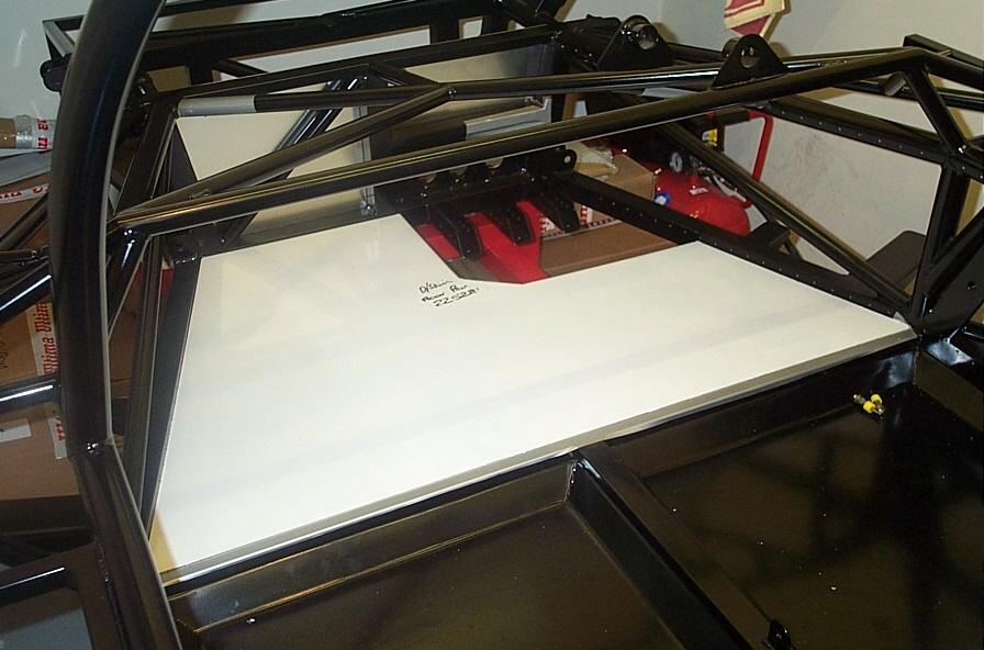
Wow, no room in there now to do any work, oops! Ahh well this shouldn't take too long. So first I located the three floor panels and placed them in the correct location on the chassis. As you can see from the piccies there is little or no fettling needed to fit any of these panels. It seemed logical to fit the panel starting from the front and working back as the front panel should obviously be flush with the front chassis rail, so that was where I started.
So to the fixing of the panels, the standard rivet spacing is again slightly awkward here but what I did was place a central rivet in the middle of the panel and work outwards from there using the standard 30mm spacing and this seemed to work well. I first drilled around the edged of the panel and then drilled the chassis accordingly. This then allowed me to fix (with skin pins) the panel to the chassis and mark the cross braces from underneath. If you get at close as you can to the rail edges with your marker pen this will give you a very good indication for the centre line of the rivets. This was done for the three rails and the rivet jig was then just placed centrally between the lines and the rivet positions marked and drilled. The panel was then repositioned, fingers crossed and the chassis then drilled...
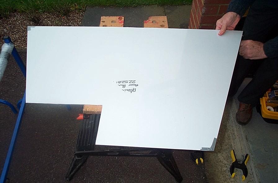
Perfect really pleased with that so on to the next panel, this one is dead simple as it is rectangular and has no cross braces. The same methods were used and once again a perfect result, well pleased. So to the largest panel to be fitted to the chassis so far, again the same principles were to be used and after some measuring and checking the first problem arose. I noticed that if the panel were to be fitted in the this position the top of the panel would foul an the main floor plan welds. Now this was not an oversight on my part (well maybe a little) but on one side of the chassis the panel cleared the welds but on the other side iit didn't weird eh!. So all stopped at this point and instead of trying to solve it there and then (it was late!) I decided to throw the towel in and give it some thought. So here's to thinking until later in the week...
Time to Flip the Chassis again...
Well the first problem to solve was the fitting of the main floor pan panel. As
you will see from earlier I was not happy with the fit of this panel. Basically
approximately 2mm needed to be removed from the overall length (due to the panel
interfering with the welds from the main floor pan). The best and only way to do
this was by hand with a file! After over two hours I was no happy with the panel
fit as it now cleared all the welds (a result, and well worth it!).
With the panel now in the chassis all the holes could be drilled, this was duly
done and the panel was temporarily fitted into place with skin pins. This then
allowed me to crawl under the dolly and mark out the position of the diagonal
cross brace (don't forget to mark it all the way along). The Rivet jig was then
just placed in the centre between the two lines (rivet jig is 20mm wide) and the
hole spacing was marked and drilled. The panel was then placed on the chassis
and the chassis drilled. Panel removed revealed a perfect straight line of hole
down the middle of the rail.
I now needed to turn the chassis back up the other way before I fit the floor
panels as this will allow me to mark the double skin panels for the cockpit
floor and the radiator area.
With the chassis now back on the dolly I could start work on the cockpit floor,
this looked like it was going to be fun as the panel needed three 90 degree
folds and various braces riveted to it to bridge the gap between itself and the
lower floor panel. This is where the confusion started, as when we unwrapped the
parts we had one panel and six braces. After studying the contents of the build
CD we realised that the position of the fold was determined by the diagonal
cross brace. The build manual suggests that you remove a section 270mm x 270mm
for the pedals, but before we did this we wanted to be more clear about this cut
out. So using the air nibbler we removed a smaller section of the panel (just
around the pedal boxes) and this allowed the panel (with a small amount of
fettling for the back corners) to fit perfectly in the chassis. The cross brace
could then be accurately marked from underneath. With the position of the cross
brace now marked it was time to mark out the full cut out (270x270). This caused
more confusion as for one we were unsure of the positioning of the six cross
braces as the manual clearly only shows four and secondly the width of the
diagonal cut appeared a lot narrower than the cut out in the manual. After some
head scratching we decided to wipe the panel clean and start again. This goes to
prove the point of the measure twice cut once rule as what we had marked
originally was completely wrong and now the cut out was looking much better.
Although we were still unsure of what to do with the braces we decided to fit
what we could see (from the build CD) to be correct, this would leave us with
two spare (both same length).
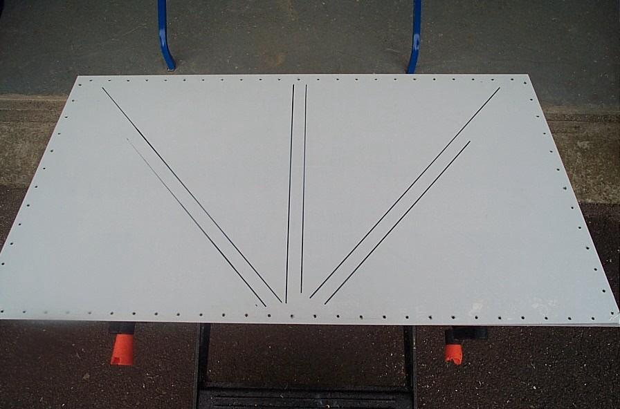
The 270mm x 270mm could now be cut and trimmed with a hand file. The three folds
were now made, these were done by hand (slowly!) with a small block of soft wood
and a dead blow hammer (Toolbox). Happy with the result it was now time to mark
all the rivet positions on the panel for both fixing to the chassis and to the
braces. All the hole are spaced 10mm in from the edge of the panel (make sure
its at least 10mm + as you don't want it to foul the edges of the panel), again
the central holes for the diagonals can be positioned using the rivet jig. Be
careful with the rivet spacing with this panel as it may be necessary to blind
rivet a couple of hole as if you don't some of the symmetry can be lost. With
the panel drilled the braces could now be positioned (they were marked first and
checked for alignment back in the chassis) and drilled with this done the panels
protective covering could be removed and the braces riveted to the panel.
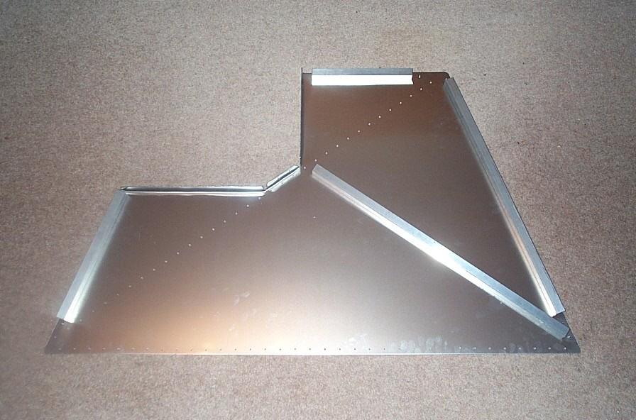
With the panel now completed it was fitted back into the chassis (looks good eh!) ready fir the holes to be drilled in the chassis. Unfortunately I had now run out of time, over the next couple of days I hope to finish fitting this panel and start on the radiator double skin. The goal is to finish all the panelling before Xmas, watch this space...
Ho, ho, ho Merry Xmas and a Happy New Year...
Hi just a quick note as the updates have been slow of late (too much food, beer and wine results in too many hangovers) to wish you all a merry xmas and a happy new year. The build has been good and bad (more of that later) over the last week or so. But the holiday season brings more family get togethers and less build time. So promise to post full update on Sunday 5th January 2003. For now here's some piccies to have a look at....