Also just a word of warning, go very careful when opening packages with scissors
as it is possible you can cut the top of your finger off (I won't publish the
pictures) as I did (that's the blood and sweat, tears next...)
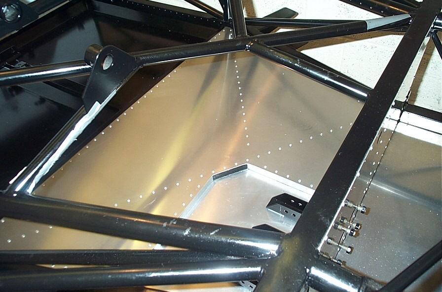
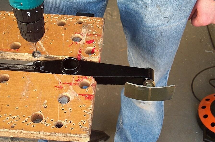
Also other work carried out was the addition of four holes drilled in the rear
bulkheads for the handbrake cables. We still have to add a couple more holes for
the gear linkage and once this has been done the rear bulkheads can be riveted
and bonded into place. So that's the next job.
I'm of to the Autosports International on Saturday so only one day of build this
weekend with updates on Monday (should be back to weekly updates now Xmas is
been and gone, as is my hangover)...
Wow what a weekend...
So on Saturday it was off to Autosports International at the NEC. This was the second year running that my father and I had attended the show. The main highlight is the Live Action Arena, where they put on a show of live action racing from carts to rally cars, damn good it was too. Inside the main halls two more highlights were waiting. The first of which could be found on the EVO stand...


Trust me this car really is something but at £316,000 its one for the lottery list only.
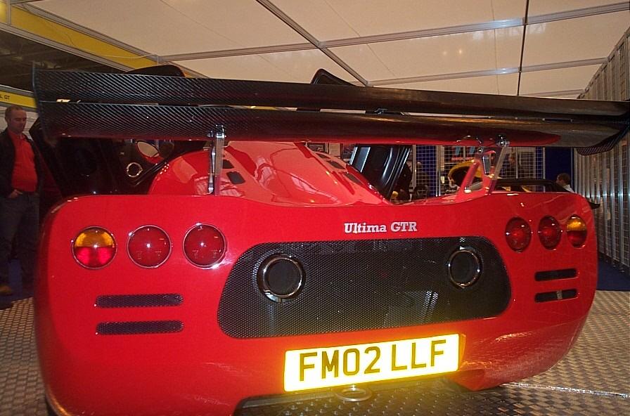
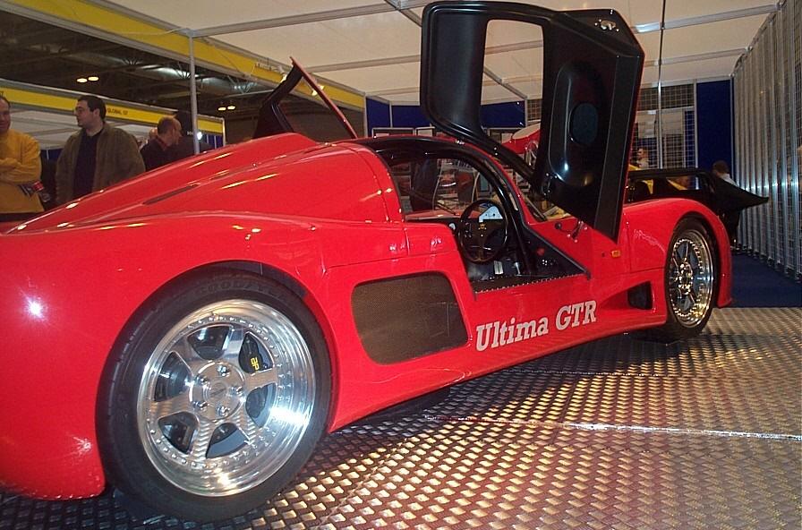
But for me the best highlight of all was watching and listening to people drooling all over the Ultima GTR and knowing that one day (soon, well maybe this year...) that the dream for me would become a reality.
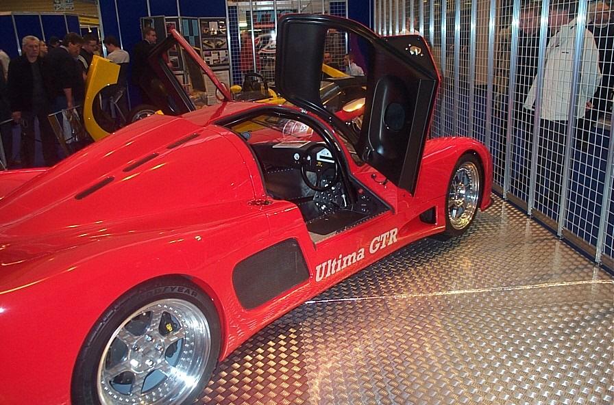
A quick chat with the boys and a few quick questions while we were at it (thanks Andy) and we were on our way...
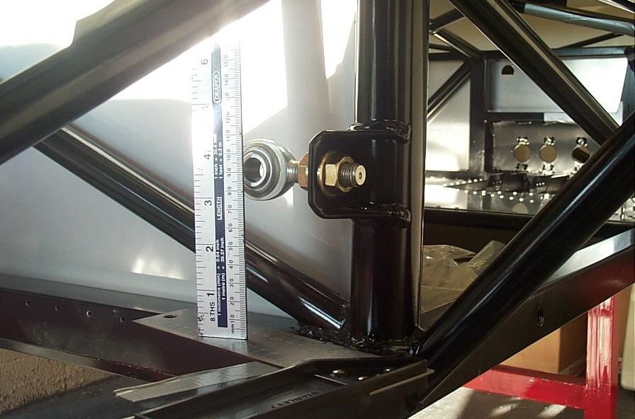
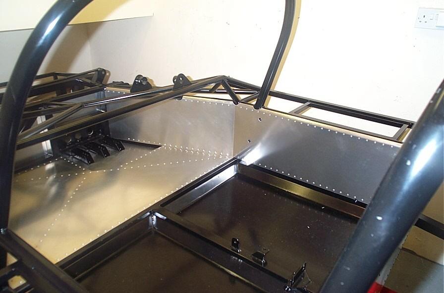
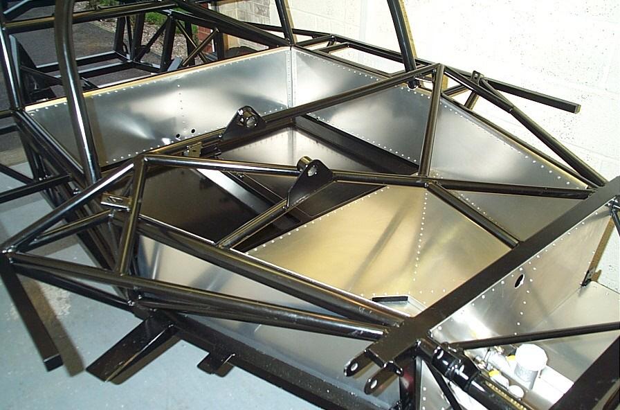
So on to Sunday then, where we had a very productive day. The first job of the day was to work out the positioning of the holes for the gear linkage in the rear bulkheads. First the height for the inner panel (cockpit) was calculated. This was done by measuring the distance from the lower rear chassis rail to the centre of the gear linkage rose joint (pic), this gave a figure of 93mm. A line was then drawn across the bottom of the panel where it meets the chassis rail as a reference and the panel was removed. The distance between the line and the bottom of the panel (19mm) could then be added to the 93mm giving you the vertical position of the hole (111mm, hope I got my maths right).
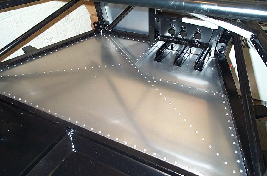
The horizontal position was a little more difficult to suss out. The difficulty is that the thread on the rose joint allows for a large degree of adjustment. So as a starter for ten we positioned the rose joint centrally in the bracket, thinking that this would give us a good deal of adjustment if it were needed. This resulted in a horizontal spacing of approx 40mm. The main concern was how far into the cockpit would the main gear linkage shaft protrude (i.e. the distance away from the side panel). The worry was that this could interfere with the positioning of the seats. So after looking at how close we could get the linkage to the side panel about 32mm we decided on a spacing of 35mm, this also avoids the hole (14mm) fouling on the folded return of the side panel (just!, good job then...). The panel was then pinned back into position and the outer panel (engine bay bulkhead) was also pinned in place. This then allowed the outer panel to be marked through the hole of the inner panel, the panel was removed and drilled. Both panels were then deburred the holes in the chassis were then treated with Waxoyl and the panels were bonded and riveted into place. A large blob of bonding agent was also placed on the diagonals to prevent the panels from 'drumming'.
Now before the bond dries the top edge of the panel needs to be napped over the top of the chassis rail. Call in the Rolls Royce engineer (i.e. let dad do it)... This was done with a good hammer and a few blocks of wood and a lot of elbow grease. But what I'm not happy about though is this...
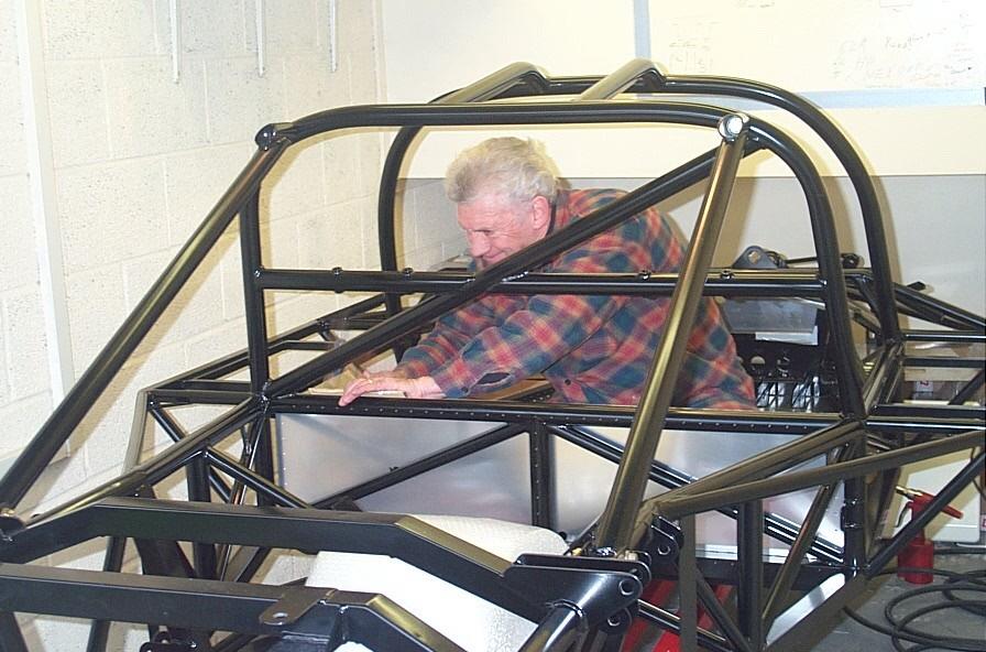
He sat in in before I did...
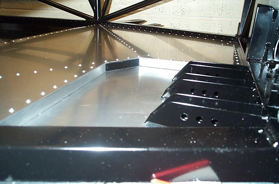
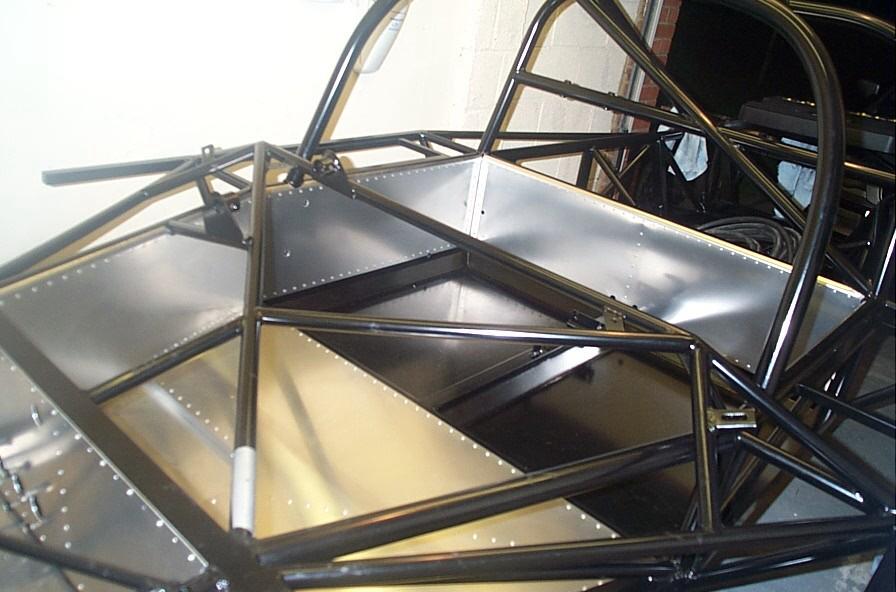
So with the rear panel completed our attention was drawn to the drivers side panel and the holes for the gear linkage. These were easily marked through the existing holes in the chassis these were then drilled (14mm). The panel was then riveted and bonded into place and before the bonding agent was dry the panel was napped along the top of the chassis rail, this is when you find out how good all those cut-outs were that you did. Pleased with the result it was time to call it a day.
Just a quick note to say that I have added a couple of new links Evo and Circuit Driver to the links page, until next time, bye for now...
The First Mile Stone is Reached...
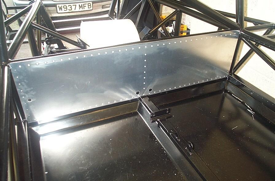
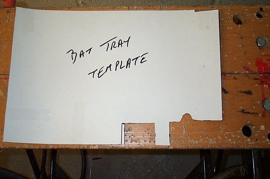
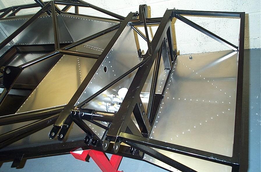
On Saturday with only a small amount of build time available I decided to fit
the battery tray, should be easy enough! Looking at the battery panel it
was obvious that once again this was a panel that would only fit once it fitted
(if you get the drift!). So once again it was time for a quick template. And
quite a template it needed to be as the tray fits around numerous chassis rails
and braces. Once happy with the fit of the template this was then transferred to
the panel. Out came the trusty air nibbler and the rough shape was cut out and
tidied up with a hand file, making sure not to go to close to the marked lines
(you can always remove more but never put it back!).
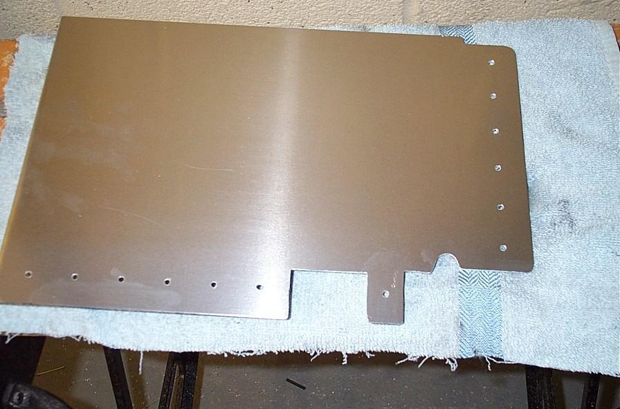
So to the first trial fit and a tight fit it was, but that's good. With the help of a mate (thanks Geoff) and about 10 trial fitments and lots of fettling the panel finally fell into place (Perfect!). Next job was to pop a handful of holes in the panel on two of the sides. I decided to mark these by hand as the 'Rivet Jig' was beginning to look a little worse for wear. The holes were drilled, deburred and the panel was placed back in the chassis, once happy with the alignment the holes in the chassis were then drilled and deburred. The panel was then bonded and riveted into place. Pleased with the results it was time to call it a day until tomorrow when we would fit the final panel...
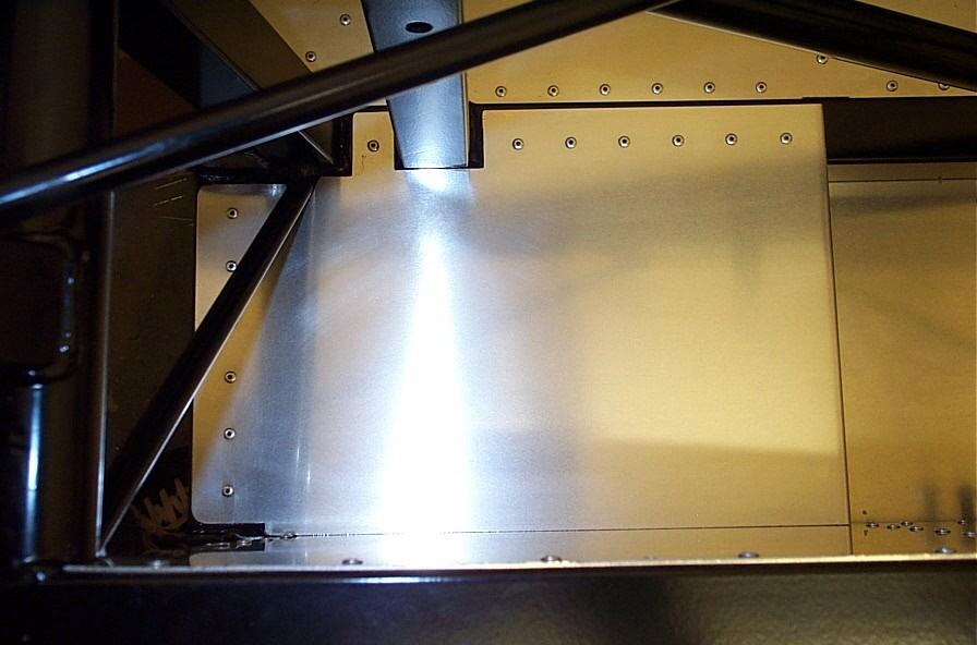
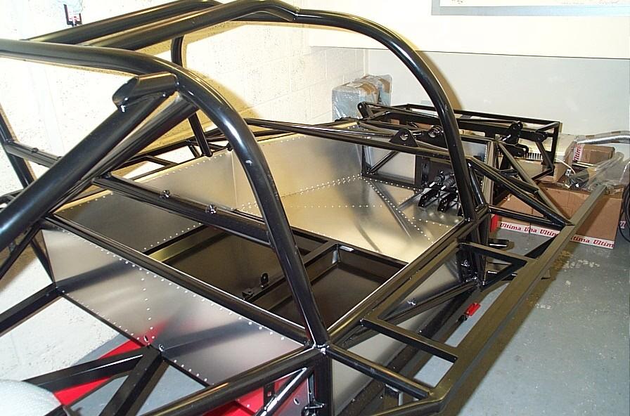
Sunday, the final side panel looms...
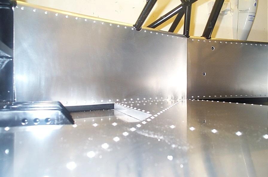
As the side panel had already been pre-fitted then just a small amount of
fettling would be needed to ensure a perfect fit. Once again it was time to call
in the king of the hand file (dad) and some 5 hours later he was finished (no,
just kidding more like 1 hour (felt like 5 though). The last panel was then
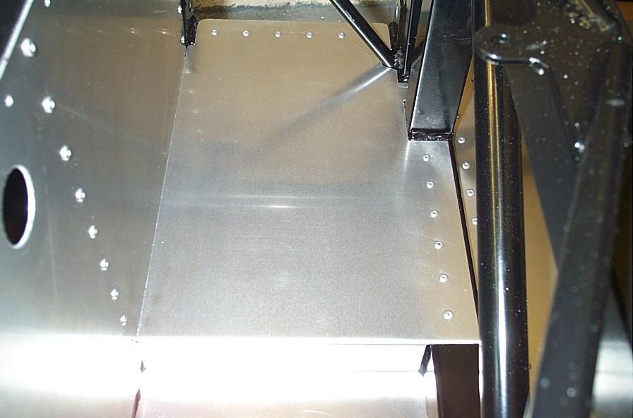
finally bonded and riveted into place and the panel was napped over the chassis
rail. This then is the end of the main panelling of the car, will I miss it, I
think not, looks good though...
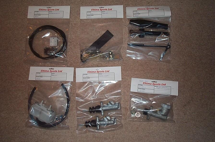
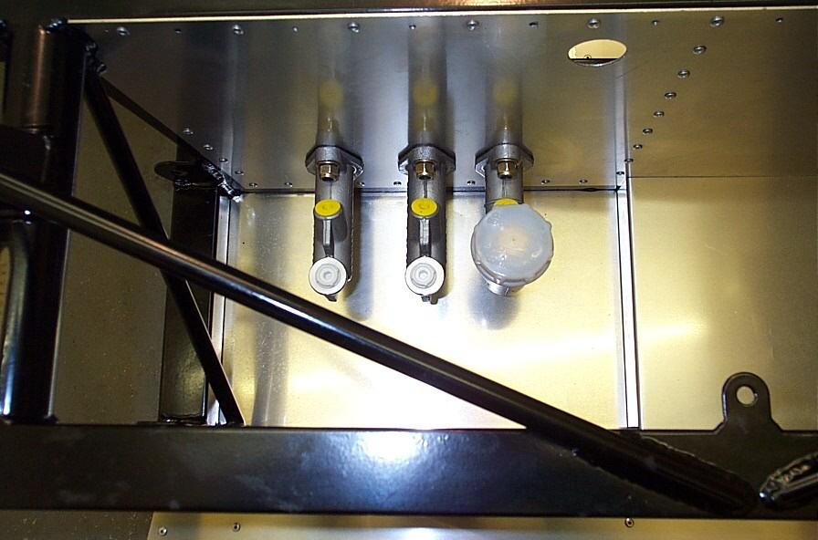
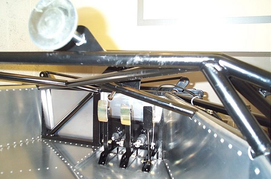
So what now? Well there was no time to stop, so onto the pedals and master cylinders it was. You can see from the pic below the time and effort that Ultima go to make this as easy task as possible, presentation/packaging is excellent. The first job is to fit the master cylinders for the clutch and the two for the brake (front & rear). These are positioned with a little sealant and bolted to the existing studs welded to the chassis with nylocs. Next it was the pedals themselves, now there are 3 possible positions for each pedal, after consulting with the factory (thanks again Andy) the positions are as follows.
Assuming you are sat in the drivers seat (on the right of the chassis):
| Pedal | Position |
| Accelerator | Front |
| Brake | Back |
| Clutch | Middle |
At this point we hit the first snag, the bolts that hold the pedals in place would not fit in the holes described due to the powder coat. Easy drill them out you say, ahh well the problem is that you can't get a drill in there not even a right angle drill or in fact any other useful tool (Doh!). Some head scratching/thinking (ooh my head hurts!) and a small discovery was made (dad again!), the handle was removed from a round needle file, this could then be easily passed through all the holes, starting from the clutch side and the holes could be easily opened out. With the bolts now fitting it was time to assemble a pedal, we started with the accelerator. Again the powder coat is a problem, this time the collar that the pedal pivots on would not go through the hole at the heel of the pedal. Now as this needs to be a near perfect fit I didn't want to attack it with a drill or file, so with a little more thinking I used a miniature wire wheel attached to a drill, this seemed to do the job a treat. The accelerator pedal was then bolted into place.
Time had now become my enemy and it was time to call it a day, as I wanted to give the garage a good clean out now the panelling had finished. Until next weekend when we bolt more bits to the chassis (car)...
P.S. There are some great new pics of Ultima's GTR demonstrator up on their site.
Brake, accelerate, steer and change gear surely NOT!
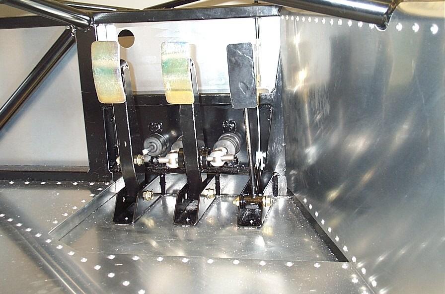
So the build continues, continuation of the pedals and accelerator cable was the
order of the day. The pedals themselves are relatively straightforward to fit.
The pictures and descriptions in the manual are very clear as there is a rather
nice exploded view of the entire system. Assembly of the clutch and accelerator
pedals are self explanatory although you will probably need to remove the clips
on the clutch and brake cylinders to allow the actuating arm to rotate thus
enabling them to be threaded onto the bias bar uj. This is were the brake is
significantly different, although assembly is still easy careful attention must
be paid to the end float of the bar to pedal, as too much will promote excessive
play in the linkage, about 1/2mm - 1mm worked for me (with a little help from
Ted). The pedals now needed to be setup for heel 'n' toeing but not having the
seat this was just a matter of guesswork for now. The clutch and brake were set
at approx 10 degrees forward (i.e. towards the driver) from the vertical and the
accelerator slightly lower (as per the manual) although this is governed mainly
by the accelerator cable which incidentally was a real ****** to fit, but
eventually we got there (although the air was blue...).
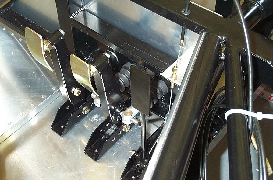
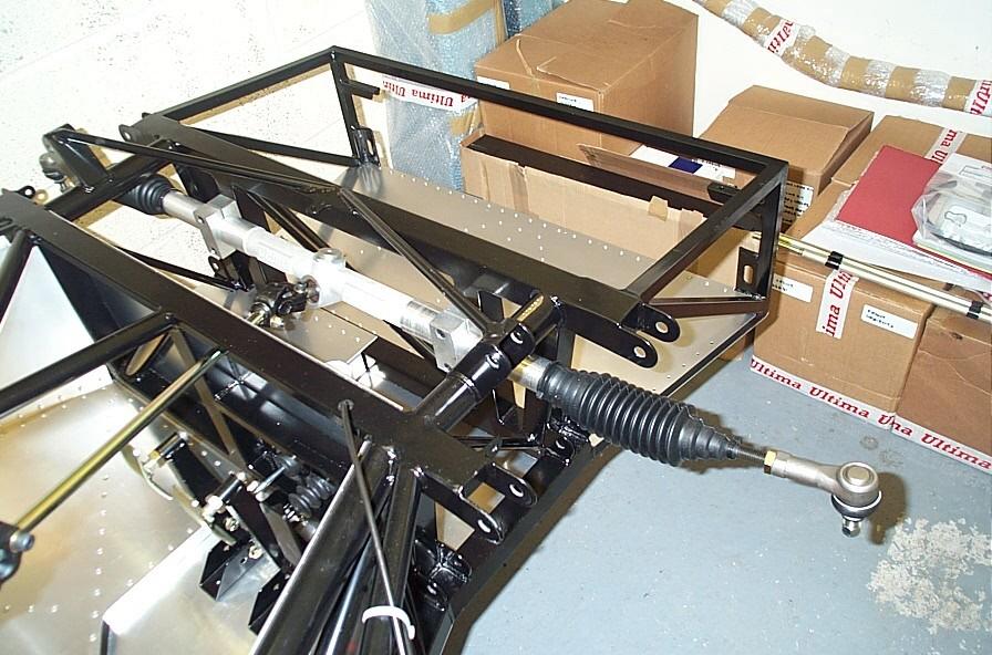
Next up was the steering rack and what a beautiful piece of equipment it is (built in house at Ultima I believe). Although its tricky to fit the universal joints onto the splines once the column and rack is in the chassis, gentle persuasion is what's needed. The lower column passes through the hole in the front bulkhead made earlier in the build, and it fits! A quick note to other builders is firstly it is possible to fit the rack upside down (embarrassing grin!, say no more) and secondly its possible to drop the retaining nylocks for the rack bearing brackets down inside the chassis ooops! Thanks goes to my wife Annette for assembling the tool of the day, a small magnet on the end of a coat hanger (patent pending!) and a calming cup of tea for my father and I. Finally the steering column needs to be polished where it passes through the bearings in the chassis (fitted earlier with the aid of some washing up liquid). With the rack and column now in place the gaiters were added and tie wrapped into position and the track rod ends were fitted temporarily onto the steering arms ready for the hubs.
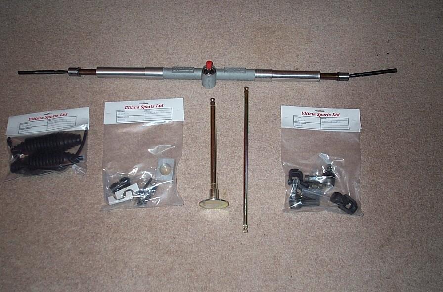
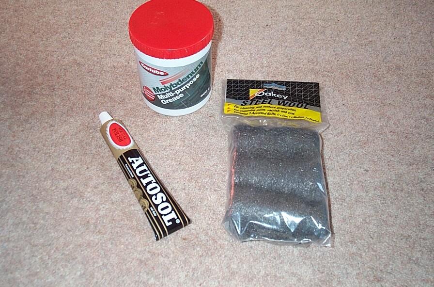
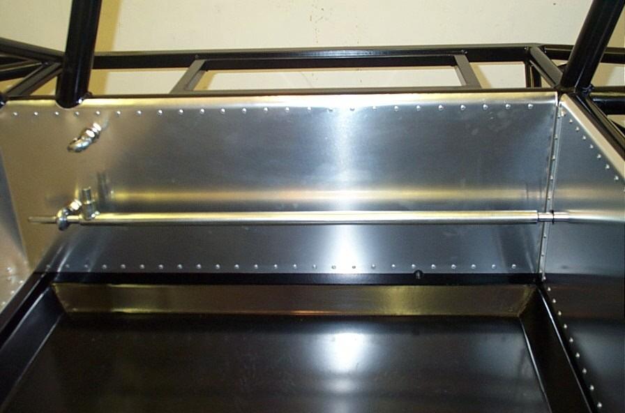
With time now running a little short it seemed pointless to start on the suspension so we turned our attention to the gear linkage, it had been hanging around the garage for some time as it was required earlier in the build for measurement purposes. First the front and rear (cockpit area) rose joints were placed into the chassis and the front gear linkage section was offered into position. First slight problem is that is was not possible to slide the linkage through the bearing as it was a little tight. Not wanting to force it (it's a bearing after all) we decided to get the polishing kit out again. Both ends of the linkage were then duly polished with wire wool and metal polish until you could see your face in it. With the rear of the linkage now in place through the rose joint it was apparent that we could not slide the linkage back far enough, as the hole in the rear bulkheads was too small to allow the oversized (i.e. non bearing part) of the linkage through (****!). Polishing would not be an option here! The hole needed to be opened out from 14mm to 20mm, this was easily accomplished with one of the stepped drills. The linkage was now be slid into place and silky smooth it was...
Before we could continue with the gear linkage it became apparent that numerous
ujs would need to be pinned into place at varying points along its length on its
way to the rear of the car. Concerned about the positioning (centrally) it was
time to call in a favour (thanks Mark!). Hopefully this will be done for next
weekend (hint, hint!) and the build will continue and maybe we will get around
to the suspension...
Just a quick note as the steering and suspension needs to be torqued at various
points, I decided to treat myself to a decent torque wrench (see
Toolbox for further details), until next time, James.