Why?, well because on Monday evening my laptop suffered a major hard drive failure (*******!, ****, **, ***!!)... Say no more, but hopefully if your reading this then we're back (thanks to Séamus for helping me recover what was left of my hard drive)...
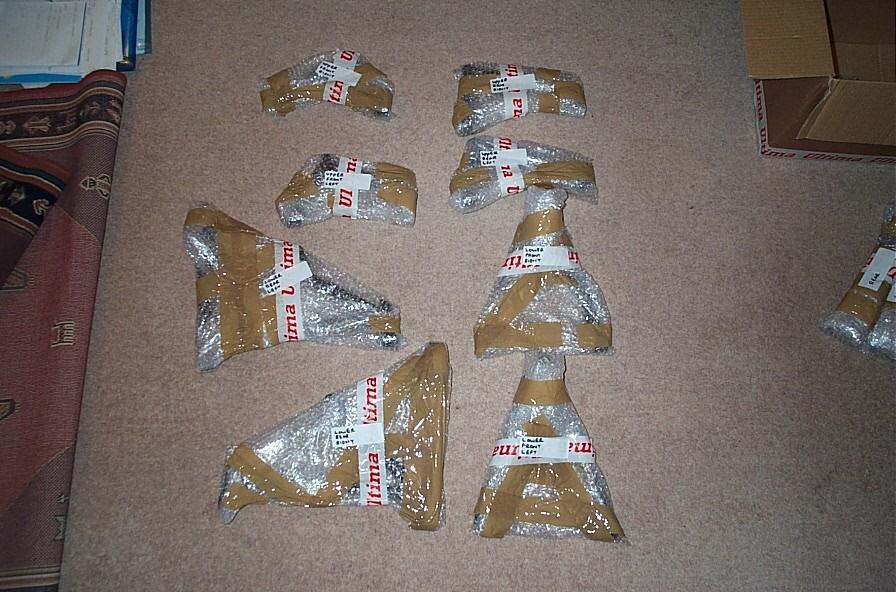
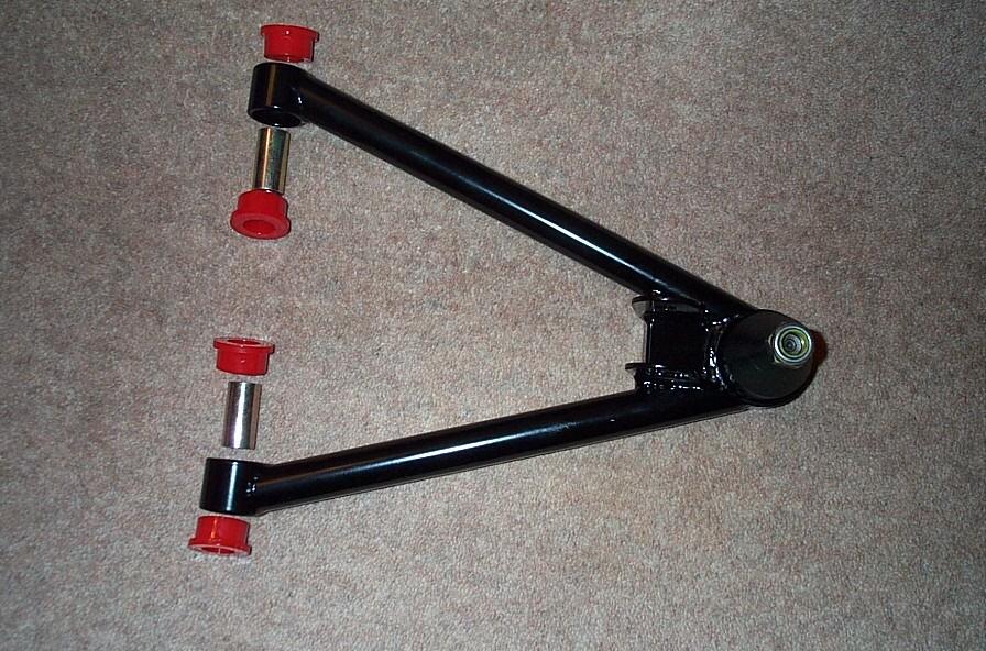
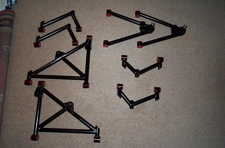
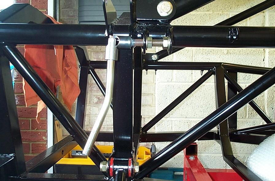
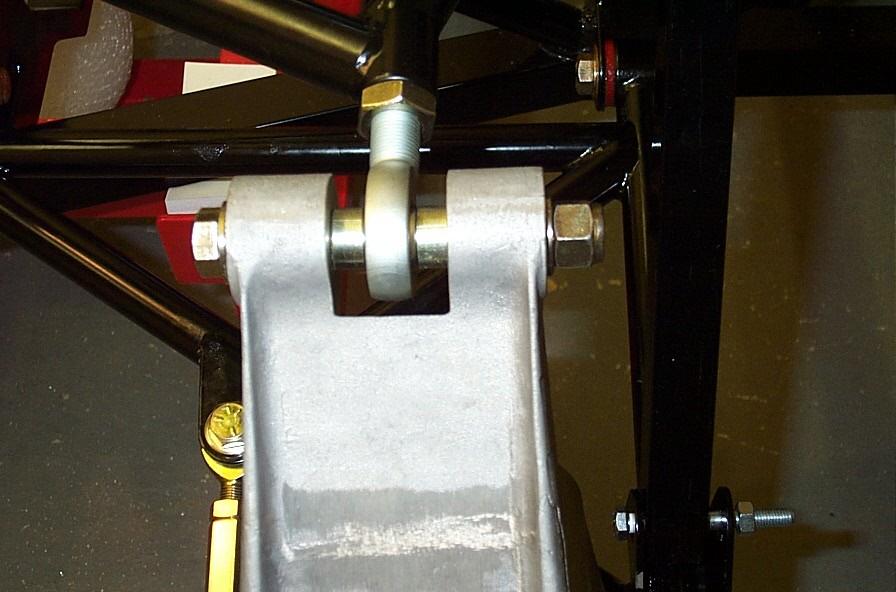
So the first job of the day is the assembly of the front and rear wishbones, be careful as these are all marked for position (i.e. front upper left etc.). These consist of a 2 bushes and a steel bearing for each corner. One bush is pressed (using the good old quick clamps (B&Q), and plenty of grease) into the housing followed by the bearing and the other half of the bush and more grease. Once this was done the wishbones were offered up to the chassis, it is at this point that you will notice that the fit is a little tight (too tight!) requiring the chassis lugs to be opened out a little. Not wanting to use a hammer and a piece of wood if I could help it, it was time for another bright idea (unfortunately I didn't have any, but my father did...). The theory was that we needed a spreader of some nature (read, a threaded bar with a couple of nuts and washers, see
pic) and the gear linkage seemed to contain those very parts. This new tool (yet to be given an official name) proved to be very useful and within a mater of minutes the wishbones were all in place not forgetting a little grease and copper ease. The front ball joints then needed to be fitted (wind them all the way in until the thread is just protruding from the back of the wishbone, thanks Andy). The rear upper rose joints can also be fitted at this time, as for positioning these are best set up at a later date.
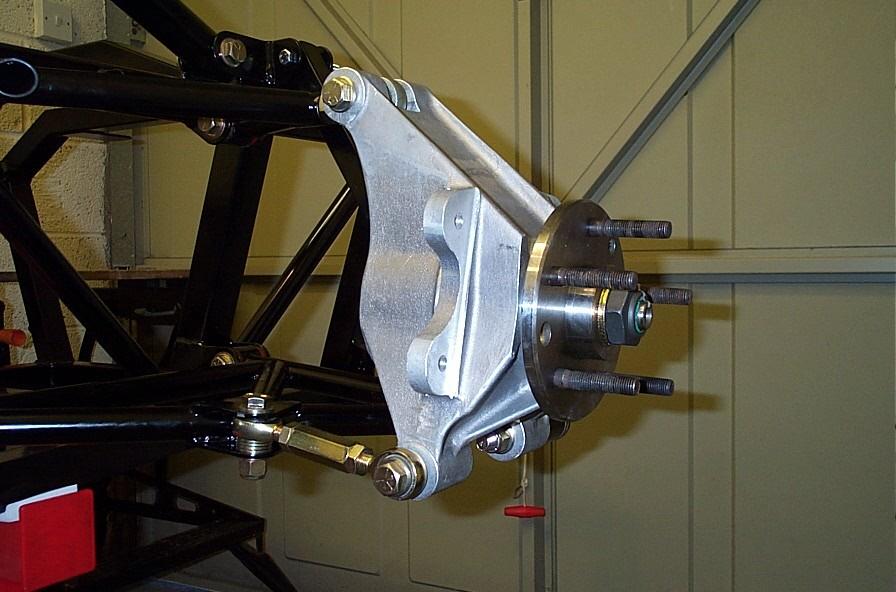
Next up were the hubs once again these are marked so be careful, first the front. These are relatively simple to fit its just a case of attempting to get the steering aligned best you can at this stage and bolting it all together. Not forgetting to bolt the steering arms to the uprights first.
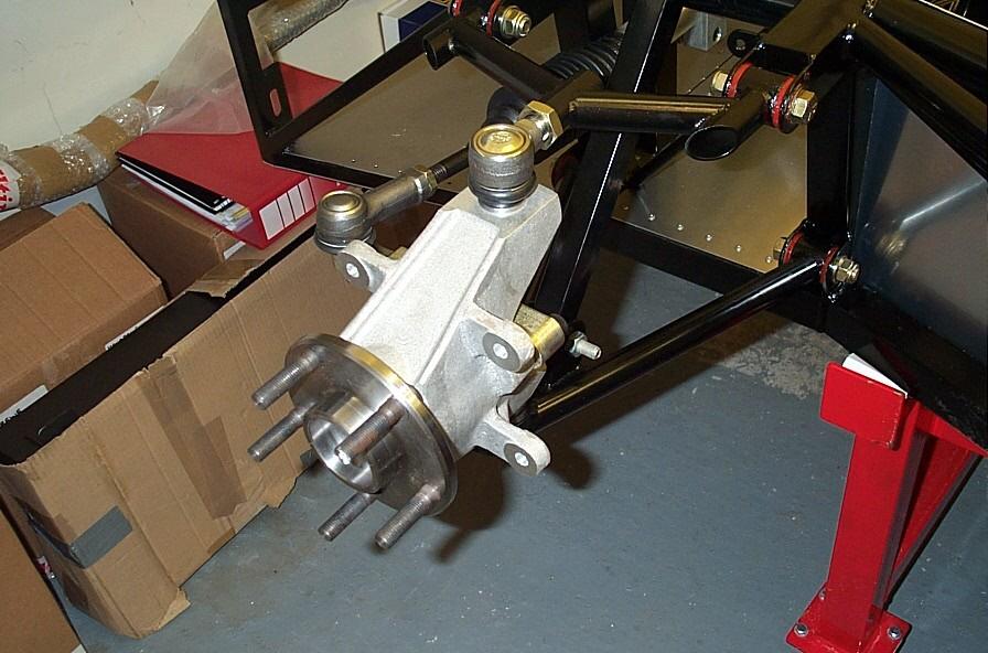
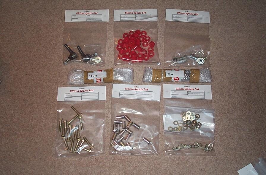
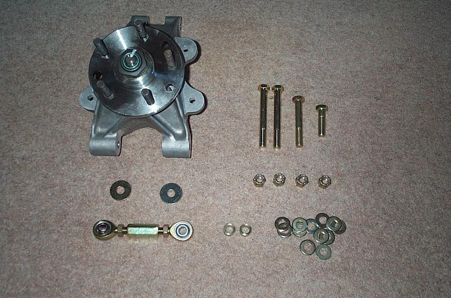
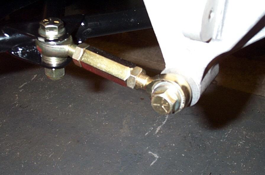
So onto the rears, these are a little more complex as there is the toe adjuster and a handful of additional washers and spacers to deal with. A complete kit for each side can be seen in the pic below. The assembly is quite simple and can be seen from the pics (just a quick note to say that the 4 large washers are not the same one is thicker than the other and the thickest goes on first as described in the manual. Also at first you will think (what do I do with all these washers?) they are required as spacers/packing for the toe in assemblies (approx 4 per side). The two large spacers fit either side of the upper rose joint between the upright lugs.
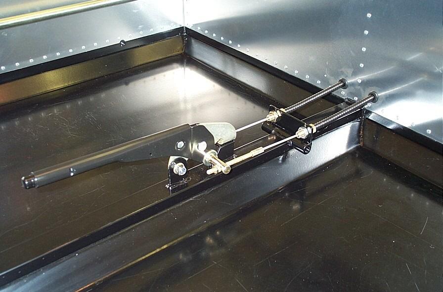
With all the suspension now in place (including the ride height bars, instead of the dampers) it was time to move on. With little time to start anything major we decided to add the handbrake this really requires no description as fitting is straight forward, just remember to pick up some grommets for the rear bulkheads. So that's the end of the build update for this week and things are looking good for my inspection (Chris) on Saturday.
Just a quick note to say that almost every week I find myself talking to the factory and just wanted to say I have found them to be nothing but enthusiastic and helpful. Thanks guys!, now where's that phone...
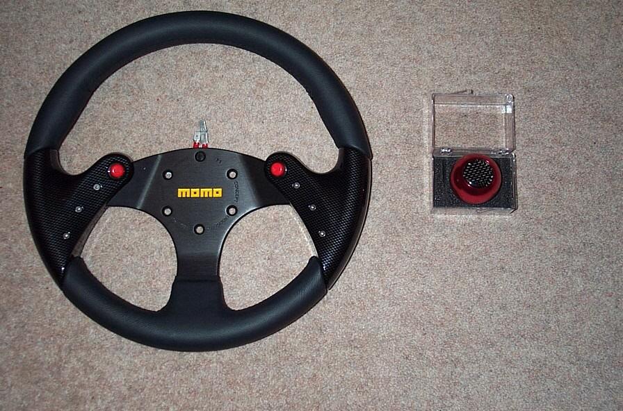
Also for some time I have been attempting to acquire a particular MOMO steering wheel. After much searching the wheel could not be sourced in the UK so it was time to go further a field. California to be precise and to
GPR who managed to source the wheel for me (thanks Dave). The wheel is a MOMO Tornado 320mm Carbon and can be seen below with the matching gear knob from
Richbrook. As these are optional/non factory items the
My Car page has also been updated.
P.S. I am running out of boxes to open in the garage, may need to order more parts soon...
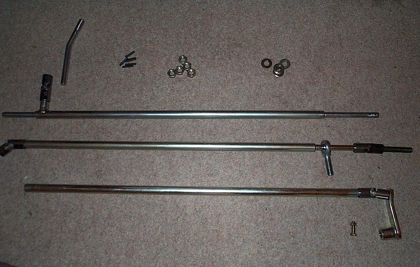
Firstly most of the linkage cannot be assembled as the fit of the ujs to the
rods is very tight (a case of it will fit, but once only, i.e. you'll never get
it apart again). This would be a bad idea as some of the assembly of the linkage
needs to take place in the chassis, where space is of course limited. So the
first job is to ensure that all the parts of the linkage can be assembled and
disassembled easily (with the help of a little grease). This was accomplished
with the use of some 'wet n dry' (medium, fine grade). Be careful if you wish to
reduce the size of the rods as these run inside the rose joint bearings. With a
fair bit of fettling the linkage was assembled and ready for drilling and
pinning. The pin requires a hole to be drilled though the uj and the rod, as the
pin was 4.4mm we decided to drill a 4.2mm hole (but I didn't have a 4.2mm drill,
an hour or so later I did (tut!)). We first piloted with a 2mm drill and then
worked our way up (carefully). This was working great until...
SNAP!
The 2mm drill broke off inside the bar/uj (disaster.., and it was). After some
cursing and swearing it was apparent that it was going to be difficult to get
this apart again in order to remove the broken drill from the uj and the gear
lever. Given the circumstances we decided at this point to call it a day
and my father took the gear linkage with him hoping to achieve something
himself...
Sunday came and I got the phone call from my father saying all was well and he
had succeeded in releasing the gear lever from the uj and had removed the broken
drill (Thanks!).
Next weekend we try again...
So the gear linkage story continues and also we get the radiator assembled and into the chassis.
The gear linkage again proved to be a pig of a job, it became apparent that a small section of drill bit was still lurking around in the incomplete hole that had been drilled previously. This resulted in further broken drills but eventually we had all the linkage drilled and ready for assembly in to the chassis. Pinning the linkage inside the chassis was not going to be an easy job. It was also apparent that if any of the positions of the rose joints were incorrect that it would be extremely difficult/impossible to disassemble once pinned. With this in mind we decided to leave the linkage until Ultima could confirm the positioning (probably when the chassis goes for its body prefit).
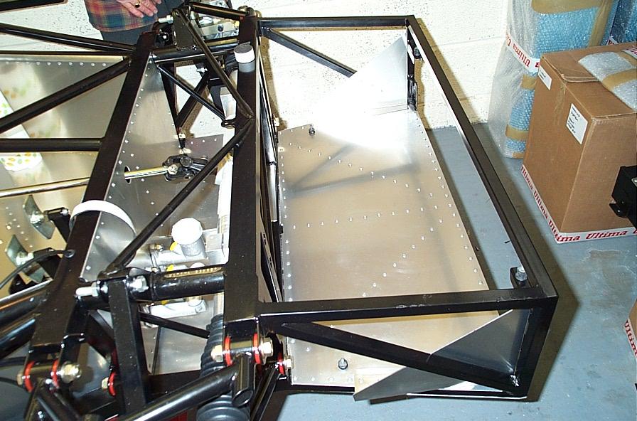
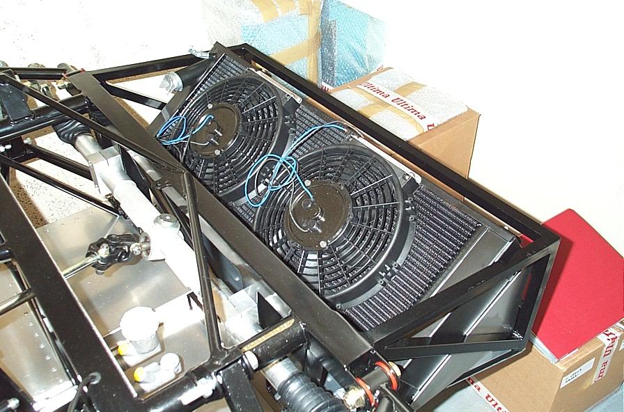
The next item to be fitted to the chassis was the radiator although this would require some assembly first. This mainly consisted of a couple of fans and some additional bracketing.
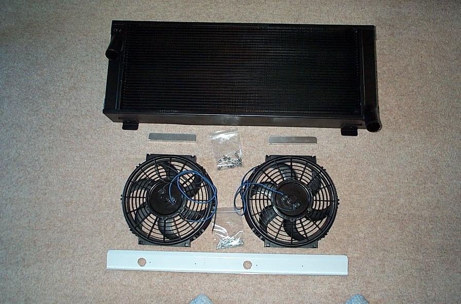
The assembly of this was relatively straight forward. First I marked the hole positions for the fans to the upper brackets(x2). The holes for the lower bracket to fan are predrilled and just need to be opened out to 6mm. The nylocs that need to be inserted into the fan housing are a little tight and needed to be tapped into place. The positioning of these nuts needs to be correct so that the fans actually rest on the radiators surface. this was achieved with trial and error (i.e. working from the top down). Lastly the radiator its self needs to be drilled this is best done very carefully protecting the vanes underneath with a scrap bit of ally.
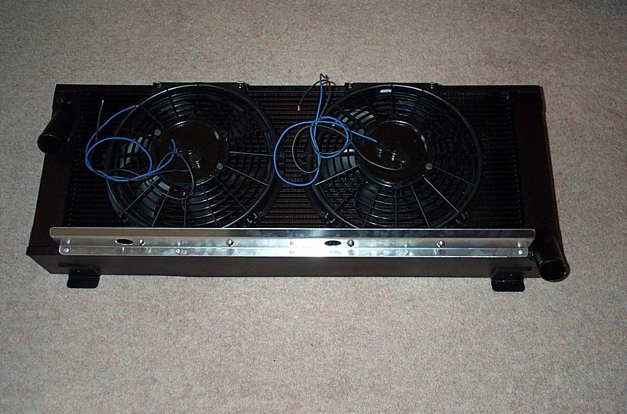
The positioning of the radiator in the chassis was the next objective as 4 holes need to be drilled in the radiator fixing tabs in the appropriate positions. This is best achieved with a little trail fitment and some accurate measuring. The task is made a little easier by the fact that the radiator is mounted on rubber ujs. With the radiator now fitting the final task was to add the side panels, these force the air into the rad instead of being lost to the sides. These panels are included with the fixing kit shown below:
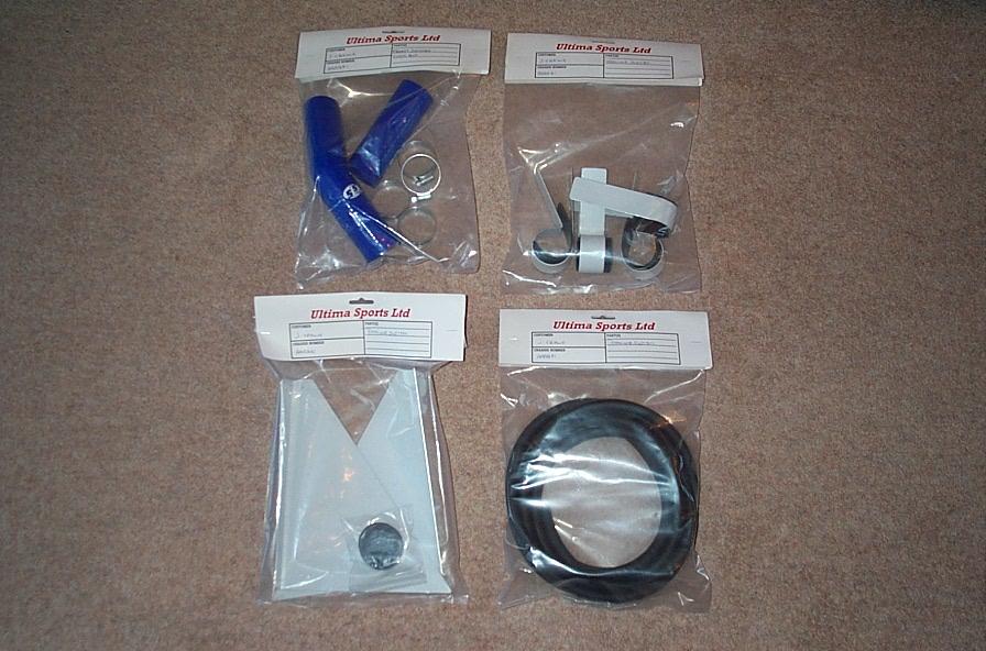
It is at this point you realise why you didn't rivet all the holes on the upper front panel (hopefully). The side panels fix onto of the existing panel and are riveted through to the chassis underneath. The panel stick out a little at the rear but this is correct as they also need to be riveted to the side diagonals as shown below. A strip of expanding foam is the applied to the diagonals of the panels to ensure a decent seal against the radiator. the radiator was the dropped into place and bolted up, job done.
As I am now running low on parts I will be calling the factory later this week and ordering the following additional parts that are required before the body pre-fit. This will hopefully be carried out by Ultima themselves as I am to scared...
Wiring Loom + Fuses
Heater Kit
Steering Wheel Boss
I also hope to be visiting the factory on Saturday to collect
the said parts and have some further discussions regarding my build, until
next week...
Well this is a little embarrassing for due to one thing or another (excuses,
excuses...) but there has been no progress this weekend on the build.
Disgraceful I know, so in an attempt to give you guys something to read (and me
something to do/write) I will relay the events of Saturday when myself and my
wife paid a visit to the factory.
The main purpose of the visit was to collect the final parts needed for the
build prior to the body pre-fit which will be carried out by the factory in
about 6 weeks. Incidentally the body was ordered on Tuesday 18th of February and
the colour is to be
red. On
arrival I was greeted by Andy as Ted was out on a test drive (it's a tough job
etc, etc...) and was quick to grab a coffee before bombarding Andy with loads of
questions. After discussions with both Ted and Andy I have decided not to fit
Air-Con to the car. This is mainly due to the fact that the car is for weekend
and track use only and also as it was fitted to my Lotus Exige and was a
complete waste of time (and power and weight). Having just saved a few quid, we
could now spend elsewhere, so after some further chatting it was decided that I
would go for the optional 'Oil Cooler' and 'Accusump Kit'. The oil cooler needs
no description but the accusump kit basically provides additional oil pressure
(from a reserve cylinder) if the pressure where to drop below a certain
threshold. A benefit of this system is that it will provide full oil pressure
while starting the car (when most of the damage occurs). This is also relative
to the engine being fitted to the car, my current reckoning says that we will be
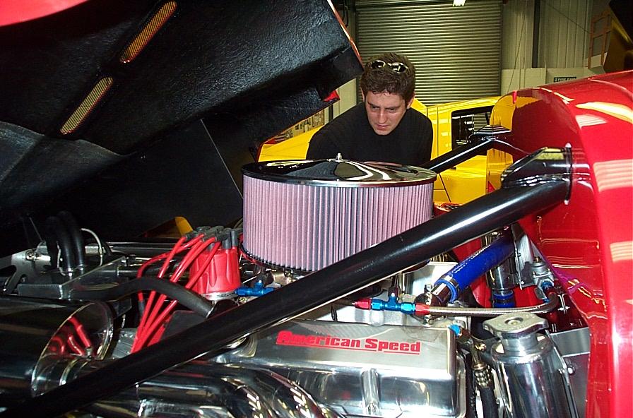
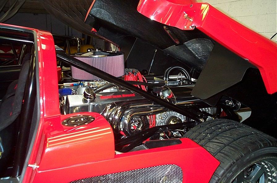
fitting and
American Speed 6.3 ltr 460 bhp 500 lbf. Choosing the engine has been very
difficult, this engine has been chosen due to its bang per buck properties and
also because an Ultima is still a very fast car with just 300 bhp (460 bhp
should be magical). I have updated the My Car
section to reflect this.
After more questions and coffee it was time to leave, but I must say how incredibly useful it is just to be able to look over other cars that that are currently under construction. While I was there I also took a few piccies, these can be seen below. I've also added a couple of new pics to the Gallery, one of a rather special looking Ultima that was at the factory on Saturday. The Ultima GTR Gallery has also recently been updated...
I am hoping to get some serious build time in this weekend.